

OEM Type B RCD Requirements Every Manufacturer Should Know
2026-11-21
For many OEMs, Type B RCDs still feel like a certification afterthought—until a prototype fails EMC or a customer’s site requires DC fault protection that a Type A unit can’t handle. The trigger points are shifting fast, especially in EV charging, HVAC drives, and industrial power. This post cuts through the noise and focuses on the requirements that actually reach your design and production line. ETEK has watched these patterns play out across multiple industries, and the lessons are worth learning before your next compliance deadline.
What Actually Changes When You Move to Type B
The first shift isn't a schedule change; it's the quiet disappearance of that internal metronome. You stop hearing the tick of every wasted minute. A delayed train becomes a chance to read a few pages, not a reason to clench your jaw. People notice you pause before replying, and you actually hear the end of their sentences.
Energy stops coming in short, aggressive bursts. It arrives slower but lasts longer. You can work through an afternoon without collapsing at 3 p.m., because you're no longer borrowing against your nerves. The odd part is that some tasks get finished faster, simply because they're not tangled up in a knot of frustration and second-guessing.
Maybe most telling is the way your body unclenches. Shoulders drop, sleep deepens, and you catch yourself enjoying meals instead of treating them as interruptions. The trade-off? A few people will misread the calm as indifference, and you'll have to decide that their urgency isn't yours to carry.
DC Leakage Paths Your Current RCD Cannot See
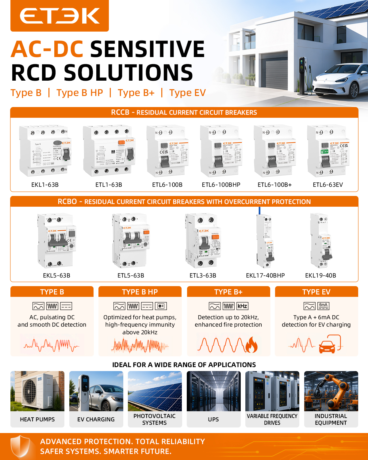
A residential installation with a string inverter, an EV charge point, or a bank of LED drivers almost always produces some residual direct current. The path is rarely obvious: it may run from a rectifier stage through the protective conductor, return via the building structure, or split between neutral and earth in ways that never show up as a simple wiring fault. Because an AC-type RCD is built around a current transformer that expects alternating flux, even a modest continuous DC component can push the core toward saturation. The result is not a device that instantly fails, but one that gradually loses its ability to see a real AC earth fault.
Solar inverters are a good example. Under low irradiance, during anti-islanding transitions, or when moisture reaches a DC bus, the leakage is often smooth and unidirectional. The same applies to EV chargers where insulation monitoring circuits and onboard converters can bleed a small direct current to earth. These currents tend to stay below the trip threshold of standard residual current devices, yet they are enough to alter the magnetic operating point of the RCD. In that state, an unrelated shock or short to earthed metal may not produce the expected disconnection.
What makes this difficult to diagnose is that normal installation testing rarely reveals it. Insulation resistance tests may still pass, and the RCD test button may still work because the test current is AC. The danger appears only when an AC fault coincides with a pre-existing DC bias. That is why mixed AC/DC installations need devices designed to detect residual DC or remain stable in its presence, rather than relying on an RCD that was never intended to see those leakage paths.
What a Type B RCD Datasheet Won't Tell You
Datasheets list residual current thresholds, voltage ratings, and trip curves, but they rarely mention how differently a Type B RCD behaves once the load contains a mix of high-frequency switching noise and smooth DC fault current. In the field, nuisance tripping often begins long before the stated 30 mA threshold is reached, because the internal fluxgate sensor can be unsettled by superimposed ripple that never appears in the manufacturer’s clean test waveforms.
Another gap is environmental drift. A device that trips reliably on a bench at 25°C may lose sensitivity or become overly jumpy when mounted inside a warm enclosure, aged by harmonics, or placed next to a drive that radiates common-mode noise. The datasheet’s single-line temperature range hides the fact that real performance is a moving target, shaped by cable capacitance, filtering components, and the specific inverter topology upstream.
Installers also learn the hard way that not every Type B unit handles all frequencies equally. Without clear guidance on derating above a few hundred hertz, a drive system can push leakage current into a range where detection becomes unstable, leaving either false trips during normal operation or delayed action during an actual fault. That practical uncertainty is rarely captured by a compliance mark alone.
Choosing Ratings Without Copying a Competitor's Spec
Ratings only carry weight when they come from assumptions you can stand behind. A competitor's published number rarely shows the test method, ambient conditions, duty cycle, or safety margin behind it. Lifting that figure means building your design on someone else's test bench. Begin with the actual operating conditions your product will face, then let the rating come out of those measurements instead of working backward from a market number.
It is also worth accepting that your published value may look different, and that can be a strength. A lower rating derived from a harsher duty cycle is more useful to an engineer than a higher one copied from a lighter test. The point is not to align with a competitor's sheet; it is to give someone a number they can rely on when they drop it into their own stress, thermal, or lifetime calculations.
If a side-by-side comparison becomes necessary, compare the method rather than the headline figure. State what was held constant, what was allowed to vary, and how the part behaved over time. Once the setup is visible, different ratings can sit next to each other without copying anything.
The Certification Evidence That Actually Survives an Audit
A certificate on the wall rarely makes it past the first hour of an audit. The evidence that holds up is the unglamorous record trail: change tickets tied to specific system updates, access reviews with dated approvals, and configuration exports that match what is actually running. Auditors look for that connection between a stated control and a routine action someone can demonstrate.
Incident reports, patch logs, and training attendance records often carry more weight than the certification document itself. When an organization can show a failed control was detected, corrected, and re-tested within a defined window, the story becomes credible. The strongest evidence links people, timestamps, and system output rather than relying on a signed statement.
Original formats and version histories matter. A screenshot with the system clock visible, an exported audit trail with checksums, or an email thread showing approval context tends to survive because it resists easy rewriting. If the evidence can be reproduced from source data during the audit, it usually holds.
Why Some Installations Demand More Than a Basic Type B
A basic Type B device covers a broad spectrum, but it starts to show limits when the installation carries mixed or high-frequency residual currents. Loads such as electric vehicle chargers, three-phase solar inverters, and variable-speed drives can introduce components that do not stay within the smooth DC or 50/60 Hz AC profile the device was primarily built to interpret. Once the fault signature becomes irregular, the protection can lose its timing edge or respond inconsistently, which is exactly where a more capable unit earns its place.
Site conditions also play a decisive role. High leakage background, long distribution paths, and areas where false trips are not tolerated push the requirements beyond a basic type. In these cases, a unit with wider frequency response and stronger noise rejection matches the real load behaviour rather than a textbook fault. The upgrade is less about the basic device being insufficient and more about the installation demanding a different performance envelope.
The practical test is often the fault waveform itself. If measurements show high-frequency AC mixed with DC offset, or if start-up and switching events create unusual residual patterns, a standard Type B is being asked to operate beyond its design assumptions. Using a device rated for that wider range removes the guesswork and keeps protection aligned with what the machinery actually does under stress.
FAQ
Type A handles AC and pulsating DC residual current, while Type F adds higher-frequency behaviour. Type B goes further by responding to smooth DC residual current as well. That smooth DC capability matters because faults downstream of a rectifier or inverter can produce a direct current that Type A and Type F devices may not detect, and that same DC can saturate the core of an upstream RCD and make it unresponsive.
Transformerless PV inverters, EV charging equipment, three-phase variable speed drives, UPS systems and some medical installations are the usual candidates. Any circuit where a rectifier or switching stage sits between the supply and the load can develop smooth DC residual current under a fault, so Type A or F protection often is not enough.
IEC 62423 is the main product standard for Type F and Type B residual current operated circuit breakers. IEC 60755 gives the general classification and tripping behaviour of RCDs. Depending on the end product, there may also be application-specific requirements, such as those covering EV supply equipment, so the product standard should be checked alongside the RCD standard.
Smooth DC can bias the magnetic circuit of a conventional RCD and drive it into saturation. Once the core saturates, the device may not respond properly to an AC residual current that would normally trip it. A Type B device uses detection methods intended to remain functional when smooth DC is present.
The exact bands depend on the standard and the specific device, but a Type B unit is generally expected to trip for sinusoidal AC residual current, pulsed DC and smooth DC within defined ranges. Smooth DC sensitivity is often specified up to around twice the rated residual operating current, while AC and pulsed DC have their own test limits.
High-frequency leakage from filters, long shielded motor cables, common-mode capacitors and the cumulative earth capacitance of the installation are common causes. If the RCD is placed too early in the circuit or the system has a high standing leakage current, nuisance trips can occur even without a genuine fault. Measuring the actual leakage profile under full load and start-up often reveals whether the issue is installation-related or a mismatch in sensitivity.
It is not enough to rely on the data sheet. Run the RCD with the real load under normal operation, inject representative AC, pulsed DC and smooth DC fault currents, and test at low and high temperature as well as under EMC stress. Also check coordination with upstream protection so that a downstream DC fault cannot blind another protective device.
Both options exist. DIN-rail modular Type B RCDs are common in panels and sub-distribution boards, while OEMs that need a compact solution can use residual current monitors or sensors with external toroids, or PCB-integrated detection stages, provided the assembly is validated to the relevant standard.
Conclusion
Shifting from a Type A or AC residual current device to a Type B is not a simple rating upgrade. The detection principle has to change because the device must respond to smooth DC, mixed-frequency leakage, and high-frequency components produced by rectifiers, drives, and battery converters. A conventional core can be pushed into saturation by even modest DC bias, which means a fault that should trip the device becomes invisible or the threshold drifts. Datasheets rarely describe that behavior. They give a nominal residual operating current but often omit how the unit behaves with superimposed ripple, temperature swings, or partial DC offset. If you are engineering an OEM product, ask for the test waveforms behind the stated performance, not just the final pass mark.
Rating decisions are similarly risky when borrowed from a competitor's bill of materials. The right choice depends on the maximum continuous DC component, expected leakage under load, ambient conditions, and coordination with upstream protection. What fits one machine may leave another installation blind during a fault. Certification evidence needs to be stronger than a folder of PDFs: auditors look for a clear thread from type tests and routine production checks to the specific design revision in the field. Some sites also require more than a standard Type B curve, particularly where DC voltages run higher, fault currents are severe, or selective tripping matters. Keeping a short internal note explaining why a particular rating and test set was chosen can save more time later than a drawer full of generic certificates.
Contact Us
Contact Person: Andy
Email: [email protected]
Tel/WhatsApp: +86 13356133008
Website: https://www.etek-china.com/