

Motorized Regulating Valve Company Key Questions to Ask Before You Buy
2026-11-21
Most motorized regulating valve failures are decided long before installation—at the quotation stage, where the wrong assumptions quietly become expensive problems. If you are comparing suppliers, a spec sheet will only tell you part of the story. That is why it pays to slow down and ask smarter questions about control accuracy, materials, fail-safe behavior, and after-sales support. At HONGSEN, we see these conversations as the difference between a valve that fits and a valve that keeps working. Here are the key questions worth raising with any manufacturer before you commit to a purchase.
Will the valve hold its claimed accuracy after your actual duty cycles?
Short answer: only if the claimed accuracy was derived from conditions close to yours. Bench accuracy is usually measured on a clean, constant-pressure loop with a fresh actuator and no thermal swings. Once the valve sees frequent reversals, partial strokes, or high-temperature batches, the original figure starts to drift. Pay attention to seat wear, packing friction, and actuator stiffness rather than the catalog number.
A better check is to run a step test on your actual load profile after the first few hundred cycles. Look for changes in hysteresis, deadband, and repeatability at low openings, not just full-scale error. If the positioner compensates only for static calibration, dynamic duty will expose gaps that a single accuracy claim cannot capture.
What does the actuator require from your control signal during low-flow operation?
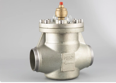
At low flow rates the actuator is operating near the bottom of its stroke, so the control signal has to be cleaner and more deliberate than it would be at mid-range. Tiny steps in the commanded position translate into measurable flow changes, which means the signal needs enough resolution to describe small movements without jumping between values. Any noise, quantization error, or unstable loop voltage tends to show up as a wandering valve position or a pulsating flow rather than a steady low-rate delivery.
The low end of the signal range also has to be calibrated with care. If the command is 4 to 20 mA or 0 to 10 V, a small offset near the zero or low-flow point can hold the actuator slightly open or prevent it from reaching the precise throttling position. The actuator expects a stable reference without slow drift, and the control system may need to apply a tight deadband or low-signal cutoff that is set just below the minimum usable flow, so it does not erase an intentional small command.
Response shaping matters just as much. During low-flow operation the actuator benefits from a command signal that changes at a controlled rate instead of snapping to a new value, because sudden moves around the seat or near the closed position can cause overshoot or oscillation. Some systems use a ramp or light filter on the signal, but that filtering has to be light enough to avoid introducing a noticeable lag between the controller output and actual stem movement.
Which failure mode is included in the base price, and which modes cost extra?
The base price is built around the failure modes that show up most often in normal operation: things like wear, basic fatigue, and simple overload conditions. These are covered without an added line item because they can be assessed with the standard data set and the usual review process.
Modes that tend to cost extra are the ones requiring specialized models or additional test data. Thermal shock, corrosion under insulation, creep, and vibration-induced fatigue usually fall into this category. If the assessment has to account for combined loading or environmental interaction, that is typically quoted separately as well.
It is less about hiding fees and more about keeping the base scope predictable. Once the failure mode moves beyond standard assumptions, the added cost reflects the extra engineering time and the need for more detailed input.
How are the seals and trim selected for the fluid you actually run, not a generic spec sheet?
We start with the actual fluid report or a sample pulled from the line, not the nominal data listed in a project spec. Concentration, pH, dissolved chlorides, trace acids, solids loading, and temperature at the seal faces all get checked against the materials we are considering. Small things like a few hundred ppm of chlorides or a cleaning chemical used once a shift can drive elastomer and trim choices more than the main process fluid.
Trim selection follows the same judgment. A 316 stainless part may be fine for the base liquid but wrong once the fluid flashes, entrains air, or carries fine abrasive particles. We look at hardness, galling resistance, and erosion allowance, then match the seal faces and seats accordingly. Elastomers are checked for volume swell, compression set, and rapid gas decompression where dissolved gas is present. If the fluid tends to crystallize, polymerize, or settle out, the seal chamber layout and flush plan get adjusted rather than relying on material alone.
The result is a seal and trim set chosen for the worst realistic condition the equipment will see, including startup, shutdown, and cleanout cycles. We would rather narrow the operating limits and document the assumptions than ship something that only works on a generic compatibility chart.
Can the company share a test curve from a recent build similar to your sizing case?
We can pull a test curve from a recent build that closely matches the sizing parameters you referenced. The dataset includes measured flow, head, and efficiency points across the operating range, so you can see how the actual hardware behaved rather than relying on a generic catalog plot.
If the exact shaft speed or impeller trim differs slightly from your case, we will note those adjustments alongside the curve. That way the comparison stays honest and you can quickly judge whether the shape of the curve, the best efficiency point, and the shutoff head align with what your system expects.
Where relevant, we can also overlay the predicted curve from the sizing routine on the same axes. The overlay tends to highlight small deviations in the rise to shutoff or the steepness past the duty point, which often matter more in practice than the nominal rating alone.
What does field access look like when the valve is installed against a wall or in a tight manifold?
When a valve is mounted flat against a wall, the first thing that disappears is usually the side clearance for a wrench or a gloved hand. If the actuator or handwheel faces the wall, even a simple quarter-turn can become a two-person job: one person squeezes in to feel the stem, another tries to pass tools from the end of the skid. A better arrangement is to rotate the bonnet or actuator orientation so the operating face points toward the nearest aisle, even if that means adding a small standoff bracket or reworking the mounting pad.
In a tight manifold, field access is less about total free space and more about which specific motion the technician needs to make. Valves packed shoulder to shoulder may still be workable if every stem, bleed port, and position indicator is visible from the same side. Once one valve is offset or tucked behind a header, the practical solution is often a remote pilot line, a cable-operated lever, or relocating the manual reset to a small local panel at the edge of the rack.
For wall-mounted installations, leaving 300 mm to 450 mm between the valve centerline and the nearest obstruction usually keeps hand operation and basic maintenance feasible. In manifold bays, alternating valve heights or angling the actuators slightly can create a visual pattern that makes each tag and position easier to read without adding much pipe length. Where that clearance cannot be achieved, direct-mounted locks and local position indicators become more important than the valve orientation itself.
FAQ
Ask for thermal duty cycle data at your maximum ambient temperature, not just the nominal motor rating. A reputable supplier will provide test curves or reference accounts from similar modulating applications.
Look at deadband, hysteresis, and repeatability under real flow conditions. The best manufacturers will talk honestly about installed performance rather than quoting a single ideal number.
Match the body, trim, seats, and seals to your exact fluid chemistry and temperature range. Request compatibility charts for each wetted component, especially if you handle corrosive, viscous, or high-purity media.
Confirm the failure position and whether it relies on a spring return, battery backup, or mechanical lock. Ask to see failure mode documentation under full differential pressure.
Ask about seal replacement intervals, stem packing access, and whether calibration requires removing the valve from the line. Designs with accessible trim and non-contact position sensing reduce downtime.
Request a clear breakdown of standard and optional features. A good vendor will configure the valve around your control signal, turndown requirements, and service conditions instead of upselling a one-size-fits-all package.
Ask about startup assistance, spare parts availability, local service partners, and expected lead times for critical components. Support quality often matters more than a small difference in initial price.
See if the company offers flow characterization or test reports from an independent lab, or can connect you with a similar facility that uses their valves in a comparable service.
Conclusion
Buying a motorized regulating valve rarely goes wrong on the published flow coefficient or the nominal accuracy. The trouble shows up later, after the valve has cycled a few hundred times under your actual pressure drop, or when the control signal drops into the low-flow range and the actuator starts hunting instead of holding position. Before you compare quotes, ask the company to prove that the claimed accuracy survives real duty cycles, not just a bench test. Also pin down what the low-flow command demands from your signal: some actuators need a minimum current or voltage resolution that your existing control loop may not provide, and that gap can turn a well-sized valve into an unstable final element.
The commercial and mechanical details matter just as much. A base price often bundles only one failure response, so ask which fail-open, fail-closed, or last-position behavior is standard and which modes cost extra. Request a seal and trim selection based on the fluid you actually run, with its real temperature, solids, and corrosion profile, rather than a generic compatibility chart. A recent test curve from a similar sizing case is a reasonable request; if the company cannot produce one, treat that as a signal about their application depth. Finally, look at the installed footprint. A valve that is easy to service on a bench may be difficult to stroke, calibrate, or replace when it is mounted against a wall or inside a tight manifold, so confirm that field access points are reachable and that the actuator orientation does not block commissioning ports.
Contact Us
Contact Person: KOPASS HO
Email: [email protected]
Tel/WhatsApp: 8613606566112
Website: https://www.hongsenref.com/