

Best Three-Phase Current Transformer for Accurate Power Monitoring
2026-09-01
Accurate power monitoring often hinges on one overlooked component: the current transformer. When three-phase systems are involved, the margin for error shrinks dramatically, and the difference between a good reading and a misleading one can cost thousands in wasted energy or undetected faults. If you’re tired of second-guessing your data, it’s time to look closer at what Xiasen brings to the table. In this guide, we’ll break down what makes a three-phase current transformer genuinely reliable, and why the right choice can transform your entire monitoring setup.
How Accuracy Class Affects Your Energy Bill More Than You Think
Most people assume the number on their electric bill is a straightforward measurement, but the accuracy class of the meter quietly sets a margin for error that can nudge costs upward. A Class 2 meter, for example, is permitted to over-register consumption by up to 2% under certain conditions—and while that sounds small, multiply it across a year of cooling, heating, and appliance use, and the difference becomes tangible. That tolerance isn't a guarantee it will always run exactly true; it's a band, and meters can sit near the upper edge without violating any standard.
What makes this harder to spot is that accuracy class doesn't act alone. Temperature swings, power factor shifts, and the natural drift of components over time can push a meter toward the outer limit of its class—or beyond it. Many utilities test samples rather than every meter, so a unit that was accurate when installed may not stay that way. Replacing an older electromechanical meter with a modern electronic one, or simply requesting a calibration check if your usage pattern doesn't match the bill, is often the only way to see whether the meter's accuracy class is working for you or against you.
Phase Angle Errors That Creep Up in Unbalanced Three-Phase Loads
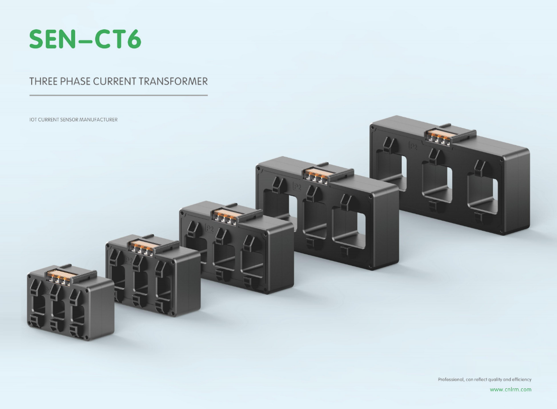
In a perfectly balanced three-phase system, phase angles sit at a comfortable 120 degrees apart, and power calculations behave themselves. But once loads become unbalanced—say, a heavily loaded phase A while phases B and C barely register demand—the assumed symmetry quietly falls apart. The phase displacement between voltage and current on each leg no longer matches the others, and small angular shifts begin to appear. These shifts are rarely dramatic, yet they accumulate in metering and protection relays, leading to readings that drift from the truth.
What often gets overlooked is how unbalanced currents create voltage drops of differing magnitudes and angles across source impedances and conductors. A utility transformer with a stiff neutral but a weak phase conductor, for instance, might see phase A current lagging by 34 degrees while phase B lags by 28 degrees under the same power factor load. That six-degree divergence is not a flaw in the load itself; it's a product of unequal line impedances interacting with unevenly distributed current. Measurement devices that assume identical phase relationships will then report phantom reactive power or incorrect energy totals.
Field technicians tend to chase the obvious culprits—loose connections, failing capacitors, undersized neutrals—but phase angle errors from unbalanced loading sneak in more subtly. A three-phase motor running single-phased for a short period, or a mixed set of single-phase loads haphazardly connected across two phases, can push individual phase angles outside the range where standard power factor correction assumes a single value. The result is not a catastrophic trip, but a slow erosion of accuracy in billing and monitoring that only becomes apparent when someone compares a revenue meter against a high-precision reference under identical unbalanced conditions.
Split-Core or Solid-Core? Let the Installation Access Decide
When you can slip a clamp around an existing conductor without shutting anything down, split-core is the practical choice—it saves hours and avoids disrupting the circuit. The hinged design opens up, fits over the wire, and snaps shut, making retrofits and tight panels far less painful. You might trade a small amount of accuracy, but that’s often worth it when the alternative is pulling new cable.
Solid-core transformers demand that the conductor pass through the window before terminations are made. That means planning ahead on new builds or cutting and re-landing cables on an existing system. In exchange, the seamless core gives you tighter repeatability and slightly better long-term stability. If the cable ends are accessible and the schedule allows, solid-core usually wins on cost and drift.
So the question isn’t which type is universally better—it’s whether you can thread the wire or only clamp around it. Let the physical access at the job site make the call. If the cable is already landed and can’t move, split-core is the only real option. If you’re starting from scratch with open conductors, solid-core keeps the install straightforward and the measurement rock solid.
Burden and Saturation: The Hidden Limits Behind Low-Current Readings
Low-current measurements often fail not because the meter lacks resolution, but because the act of measuring inserts a small series voltage drop known as burden voltage. In a circuit that operates on a few hundred millivolts, a burden of even 200 mV from a shunt or current-sense resistor can starve the load and shift the actual current downward. The reading then reflects the altered circuit, not the original one.
Saturation adds a second, subtler limit. Magnetic current sensors and current transformers rely on a core that must remain linear. At very low primary currents, the magnetizing branch can consume a disproportionate share of the signal, and any residual DC bias or previous overload can push the core toward a nonlinear knee. The result is a reading that is not just small, but distorted in a way that calibration at higher currents cannot fix.
The practical fix is rarely to buy a more sensitive meter. It means choosing a feedback ammeter or a nulling technique that drives the burden voltage toward zero, or selecting a core material and winding arrangement that keeps the flux density well below saturation at the lowest expected current. Without addressing these hidden limits, a six-digit display can still report a number with three digits of error.
Matching CT Ratios to Meter Inputs Without Losing Resolution
Matching a current transformer's ratio to the meter's rated input is not just about electrical compatibility—it's about preserving measurement resolution under real operating conditions. If the CT secondary is rated for 5 A but the normal load only pushes 0.5 A through the meter, the analog-to-digital converter spends most of its time in the bottom tenth of its range. Quantization error becomes a much larger fraction of the actual signal, and small load fluctuations can disappear entirely. This loss of resolution shows up as unstable readings, poor low-end accuracy, and difficulty detecting subtle changes in current draw that might indicate developing faults.
A practical approach is to select the CT ratio so that the maximum sustained load current corresponds to roughly 60–80% of the meter's full-scale input, while still allowing headroom for short-term overloads. For example, a feeder with a known maximum continuous current of 80 A would pair well with a 100:5 CT, since 80 A on the primary produces 4 A on the secondary—80% of the meter's 5 A range. But if the same feeder normally runs at only 20 A, that same 100:5 CT generates just 1 A, and the meter operates in the bottom 20% of its range. In that case, switching to a 60:5 or even 50:5 CT would push the normal operating point closer to mid-scale, recovering lost resolution without exceeding the CT's short-time thermal limits.
Modern digital meters often advertise extremely wide dynamic ranges, which can create a false sense of security. The hardware still has a fixed bit depth, and every unused bit above the normal operating point is wasted resolution. Ignoring CT-to-meter matching while relying on 'wide range' capability means low-load measurements inherit a coarser granularity than the datasheet suggests. Field verification matters: compare the actual CT ratio, the meter's nominal input, and the typical load profile before finalizing a design. A one-size-fits-all CT ratio rarely survives contact with the real distribution network.
Shielded Leads and Grounding Practices That Preserve Signal Integrity
Shielded leads do more than block stray interference—they create a controlled path for return currents that keeps your signal clean from source to load. Without proper grounding at both ends, though, that shield can turn into an antenna, radiating noise instead of containing it. The trick is to tie the shield to a low-impedance ground reference at the driver side, and if you must ground the far end, use a capacitor to pass high-frequency noise while blocking ground-loop hum.
Many engineers treat grounding as an afterthought, bolting everything to the chassis and hoping for the best. But signal integrity lives and dies by the quality of that ground path. A star-ground topology works well for low-speed designs, while high-speed signals benefit from a solid ground plane under the traces. Mixed-signal boards need separate analog and digital grounds, joined at a single point to prevent digital switching noise from creeping into sensitive analog front ends.
The real world rarely matches the schematic, so verify your grounding with a field probe or spectrum analyzer. You might find that a floating shield on a cable is picking up motor drive noise, or that a ground trace too narrow is causing voltage drops that shift your reference level. Small changes—like shortening the ground lead, adding a ferrite bead, or re-routing a return path—can restore a clean eye diagram and drop the bit error rate dramatically.
FAQ
Accuracy class is the starting point—look for Class 0.5 or better. Beyond that, the core material and burden rating matter just as much, because a mismatched burden can quietly eat away at your measurement precision.
Match the primary current rating to your expected maximum load rather than the breaker size. Oversizing by more than 50% often hurts accuracy at lower currents, so leave some headroom but don't go overboard.
Yes, and it's common in retrofit jobs. Just make sure all three have identical ratings and are mounted with the same orientation, or you'll introduce phase imbalance into your readings.
The burden defines how much voltage the CT develops for a given secondary current. If the actual burden exceeds the CT's rated burden, the core saturates early and the output becomes non-linear—especially at higher currents.
For most energy management tasks, yes. Split-core models in Class 0.5 or 0.5S can hold their own against solid-core units, provided the mating surfaces stay clean and the latch closes fully.
Core permeability shifts with temperature, which changes the ratio error slightly. Quality CTs use grain-oriented silicon steel or nanocrystalline cores to keep that drift within the accuracy class across a wide operating range.
Reversing secondary leads on one phase, leaving the secondary open while current flows, and routing CT secondary wires next to high-voltage cables are the big three. All are easy to avoid but common enough to cause headaches.
Rogowski coils shine in tight spaces and high-current applications because they don't saturate. However, they need an integrator and careful shielding, so for a straightforward meter panel, a precision CT usually wins on simplicity and cost.
Conclusion
When spec'ing a three-phase current transformer for accurate power monitoring, most people fixate on the accuracy class printed on the label. That number alone hides a more uncomfortable truth: a 0.5-class CT may seem close to 0.2, but over a year of unbalanced loading, those small percentage errors multiply into real money on the bill. Phase angle errors are especially sneaky in three-phase systems where loads shift unevenly across phases. A CT that measures current magnitude perfectly can still misreport true power because the phase displacement between voltage and current is off by a fraction of a degree. In low-current or partial-load conditions, burden and saturation limits matter more than the nameplate ratio. If the CT core starts to saturate because the secondary burden is too high, you lose the very readings you need for energy management. That's why the choice of split-core or solid-core isn't just about convenience—it's about whether the installation can actually accommodate the sensor without compromising performance.
Once the CT itself is selected, the details of integration decide whether you keep that accuracy. Matching the CT ratio to the meter's input range avoids losing resolution at the low end, where many energy logs go fuzzy. Shielded leads and a solid grounding scheme are not afterthoughts; they protect the small secondary signal from noise that can otherwise corrupt the data before it ever reaches the meter. The best three-phase current transformer, then, is not the one with the flashiest spec sheet. It's the one that holds its accuracy under real unbalanced loads, fits the physical installation without forcing compromises, and keeps the signal chain clean from the CT terminals all the way to the meter input. That combination is what actually shows up as correct kWh readings on your next bill.
Contact Us
Contact Person: Liu Mengyang
Email: [email protected]
Tel/WhatsApp: 8618727589233
Website: https://www.cnlrm.com/en/